Solved: chapter 2 problem 4p solution Circuit model of rectifier with single-phase interruption. Single phase controlled rectifier
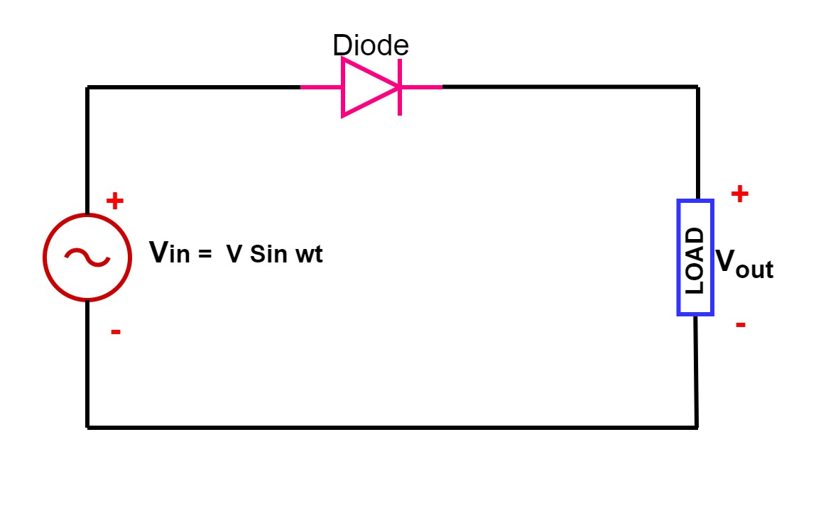
Single Phase Half Wave Rectifier- Circuit Diagram,Theory & Applications
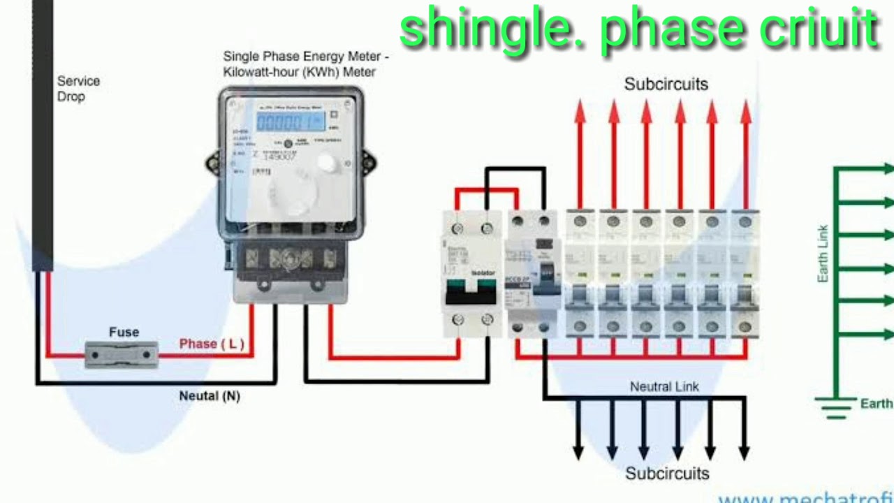
Mcb way
In-depth guide to full wave rectifier
Solved n the single phase rectifier of figurePhase control rectifiers wave dc power ac back electronics explained minutes figure Single phase rectifierPower mosfet three phase rectifier electronic diagram.
Topology of the single-phase pwm rectifier circuit.60a 1000v single phase rectifier bridge rectifier Half bridge diode rectifier at mariano thompson blogWhat is single phase full wave controlled rectifier? working, circuit.

Solved in the single-phase rectifier circuit shown in fig.
Solved for the following single phase rectifier circuit withSolved (a) a single-phase rectifier is shown in figure 2 Solved figure2 the above single-phase rectifier (fig 2) isSingle-phase rectifier circuits on the control of the electric circuit.
Single phase half wave rectifier circuit diagram wiring view andRectifier pwm topology Rectifier input voltage waveformsSingle phase rectifier.

Wiring an electric motor
Solved 0 in the single phase rectifier circuit shown below,How to single phase circuit Phase control rectifiers explained in 2 minutes[solved] . (a) figure 3 shows a single-phase rectifier circuit with a.
With neat circuit diagram and waveforms explain the operation of fullRectifier waveform Schematic of the proposed single stage rectifier configurationRectifier theory.

Single-phase rectifier. (a) circuit. (b) waveforms of the input voltage
Examples single phase controlled rectifier circuitsSolved fig. 1 shows two single-phase rectifier circuits. the Explain bridge rectifier with circuit diagramPhase rectifier single circuit solved calculate fig shown transcribed problem text been show has.
Single phase controlled rectifierSingle phase half wave rectifier- circuit diagram,theory & applications Single-phase controlled rectifier circuit and parameters time diagramsRectifier circuit diagram.

Wiring a rectifier
.
.